






Main Components of Hydraulic Control Valves Explained
Author:bohansi Time:2026-07-31 14:21:49 Click:125
Hydraulic power moves the world's heaviest machines, and the hydraulic control valve is the component that decides where the oil goes, how fast, and at what force. In our assembly and test cells, a valve that looks identical on the outside can behave completely differently inside, because the internals define performance. For buyers specifying fluid power systems, knowing the core components removes the mystery and helps you question a quote intelligently. This article breaks down the parts that make a hydraulic valve work.
The Valve Body and Ports
The body is the machined block that houses every other part and defines the hydraulic control valve envelope. Ports are the drilled passages where pressure, tank, and working lines connect, labeled P, T, A, and B on a standard directional control valve. The precision of these bores matters: a body with poor surface finish or out-of-round lands leaks internally and heats the oil. A serious hydraulic manufacturer hone-finishes bores and pressure-tests each body, because a leaky casting cannot be fixed downstream by a better spool.
The Spool and Lands
The spool is the sliding core that shifts to connect or block ports. Its machined sections, called lands, cover and uncover flow paths as it moves. Spool fit is a tight balance: too loose and the valve bypasses oil; too tight and it sticks under load. In a directional control valve, spool position decides whether a cylinder extends, retracts, or holds. We have seen downtime traced to a single scored land from contaminated fluid, which is why filtration upstream of the valve is non-negotiable on any machine we build.

Actuators: Solenoid, Manual, and Pilot
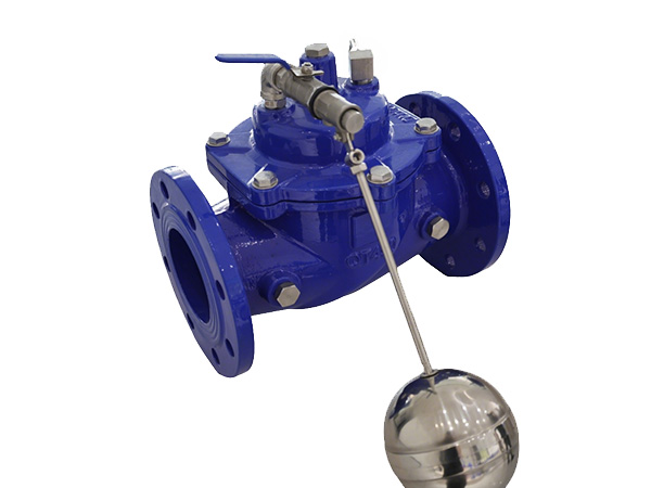
The actuator is what moves the spool. A solenoid hydraulic control valve uses an electromagnet to shift the spool on an electrical signal, the standard choice for automated machines. Manual levers suit simple or backup control, while pilot operation uses system pressure to shift a large spool that a small solenoid alone could not move. For B2B buyers, actuator choice drives voltage, response time, and environmental rating. A supplier that stocks both 12 VDC and 24 VDC coils, plus pilot versions, keeps a plant running when a coil fails at shift change.
Springs and Detents for Return and Position
Springs return the spool to center or to a default port when the actuator releases, a safety feature on many circuits. Detents mechanically latch the spool in position without holding current, useful on mobile equipment. The spring rate must match the spool travel and pressure so the valve shifts reliably but does not require excessive force. A hydraulic manufacturer tunes these in test, because a weak return spring causes drift that operators experience as sluggish or wandering cylinders.
Pressure and Flow Control Elements
Beyond direction, valves manage force and speed. A pressure control valve such as a relief or reducing valve uses a spring-loaded poppet to cap or set pressure and protect the pump from overload. A flow control valve restricts area to set actuator speed independent of load. In compact designs, these functions nest inside one body with the directional section. Specifying the right relief setting is critical: too low and the machine lacks force, too high and hoses and seals fail. We always verify relief calibration on the test bench before shipment.
Seals, Tolerances, and the Role of the Manufacturer
Seals at the spool and end caps contain pressure and keep contamination out. Material must suit the oil and temperature: nitrile for standard duty, viton for heat, and polyurethane where wear is high. Tolerances between spool and bore are typically measured in microns, which is why a capable hydraulic manufacturer controls grinding and lapping in-house rather than outsourcing critical finishes. When sourcing, ask about the test report: a valve that left the cell with a documented leakage and shift-pressure check is worth more than a cheaper one with none.
Frequently Asked Questions
What is the difference between a directional and a pressure control valve?
A directional control valve routes flow to decide actuator motion, while a pressure control valve sets or limits force. Many circuits use both in one manifold.
Why does my hydraulic valve get hot?
Internal leakage past a worn spool or land recirculates oil through the relief, dumping power as heat. Tightening tolerances and clean fluid fix most cases.
Can I replace just the solenoid coil?
On most designs yes. A standard coil unscrews from the actuator, so a hydraulic manufacturer that stocks coils avoids a full valve change-out.
How do I size a hydraulic control valve?
Match the rated flow and pressure to the actuator demand, then pick the spool that gives the needed ports and function without excessive pressure drop.
Conclusion
A hydraulic control valve is a precision assembly of body, spool, actuator, springs, and control elements working together under high pressure. Understanding these components lets a buyer judge a quote on substance, not just price, and choose a hydraulic manufacturer that controls its own finishing and testing. Specify to the real flow and pressure, keep the oil clean, and the valve will deliver reliable force and direction across a long, productive service life.
References
1. Merritt, H. E. "Hydraulic Control Systems." John Wiley & Sons, 1967.
2. Manring, N. D. "Hydraulic Control Systems." John Wiley & Sons, 2005.
3. Watton, J. "Fluid Power Systems: Modeling, Simulation, Analog and Microcomputer Control." Prentice Hall, 1989.
4. Akers, A., Gassman, M., and Smith, R. "Hydraulic Power System Analysis." CRC Press, 2006.
 HOT PRODUCT
 CONTACT US