


Structure of non rising stem resilient seated gate valve
Author:bohansi Time:2026-06-23 22:32:58 Click:70
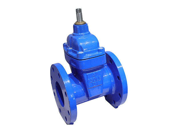
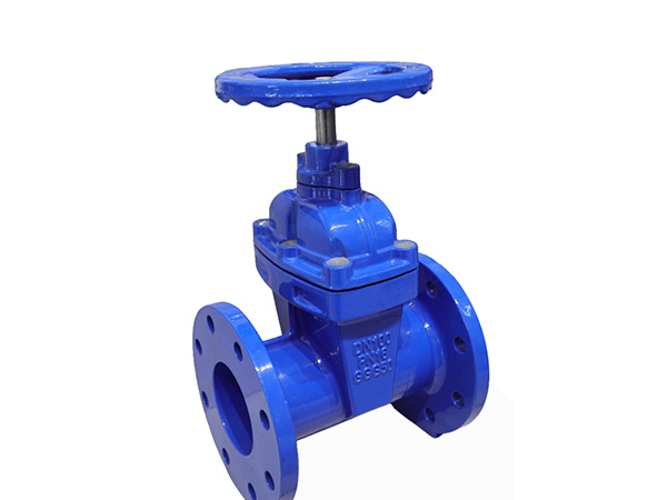
The non rising stem (NRS) resilient seated gate valve is a modified structure of the standard resilient gate valve. Its core design feature is a built-in drive nut inside the bonnet, which converts the rotary motion of the valve stem into vertical lifting movement of the rubber-coated gate without extending the stem outward. The whole assembly can be divided into six major component groups: valve body, gate assembly, internal drive stem assembly, bonnet, operation handwheel mechanism and sealing auxiliary parts. Every structural part is optimized for buried installation and narrow pipeline space (Carter, 2022).
1. Valve Body
Made of high-strength ductile iron, it forms the main flow channel and installation base of the valve.
Internal cavity: Full bore straight passage with smooth inner wall to reduce flow resistance; the metal valve seat is integrally cast inside the body for matching with the rubber-coated gate.
Connection ends: Optional flange, grooved or threaded ports to match different pipeline construction types.
Bottom structure: Integral bottom cover with sealing gaskets, convenient for internal sediment cleaning and gate disassembly during maintenance.
Anti-corrosion treatment: Inner and outer surfaces coated with food-grade epoxy paint to adapt to tap water, fire water and underground humid environments.
2. Rubber Lined Gate Assembly
This is the core sealing component shared by all resilient seated gate valves.
Gate plate base: Ductile iron casting as the support skeleton.
Integral EPDM rubber cladding: Fully wraps the entire gate surface. When closed, elastic rubber closely fits the body seat to realize bidirectional zero leakage; tiny sediment particles can be wrapped temporarily without permanent leakage.
Internal thread sleeve: Embedded on the top of the gate, matched with the drive thread of the valve stem, used to receive lifting power from the rotating stem.
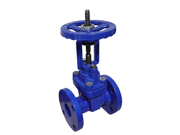
3. Non Rising Stem Drive Core (Unique NRS Structure)
This part distinguishes NRS valves from rising stem types.
Valve stem: Only rotates without vertical lifting. Its lower section has external trapezoidal threads that mesh with the thread sleeve on the gate; the upper smooth shaft extends out of the bonnet to connect the handwheel.
Fixed drive nut (internal limit sleeve): Mounted inside the bonnet chamber to restrict the stem’s vertical displacement. The stem only spins in situ, and the gate moves up and down along the stationary stem threads.
Stem packing set: Multiple layers of flexible graphite packing installed between stem and bonnet gland to prevent external water leakage at the shaft penetration position.
Gland flange & compression bolts: Used to compress packing and adjust shaft tightness during maintenance.
4. Bonnet
Cast ductile iron cover fixed on the top of valve body by flange bolts.
Enclosed inner cavity: Seals the stem thread and drive nut from external dust, rainwater and underground sludge, avoiding thread rust and jamming.
Top boss: Reserved shaft penetration hole, equipped with packing gland structure.
No high protruding structure: Overall height remains unchanged whether the valve is fully open or fully closed, suitable for shallow valve wells and narrow pipe shafts.
5. Top Operation Indicator & Handwheel Assembly
Handwheel: Cast iron wheel for manual rotation; large-diameter handwheel reduces operation torque for big size valves.
Position dial indicator: Installed on the top bonnet. The pointer rotates synchronously with the stem to display open/half-open/closed status, replacing the visual stem lifting mark of rising stem valves.
Limit stop block: Built into the indicator housing to restrict the rotation range of the handwheel, preventing over-opening or over-closing that damages the rubber gate.
6. Auxiliary Sealing & Fastening Components
Body-bonnet gasket: Rubber flat gasket between valve body and bonnet flange to stop medium leakage from the middle flange.
Stainless steel bolts & nuts: Anti-rust fasteners for connecting all split parts.
Optional extension rod interface: For buried valve wells; a long operation rod can be installed on the stem top to realize ground surface remote operation without excavation.
Working Principle Corresponding to Structure
When turning the handwheel clockwise, the valve stem rotates in place. The threaded sleeve on the gate slides down along the stem thread, pushing the rubber gate to press against the valve seat for shut-off. Rotating counterclockwise drives the gate upward to open the flow channel. Throughout the whole process, the stem never stretches out of the bonnet, maintaining a fixed overall height.
Structural Advantages Brought by NRS Design
Fixed total height, no extra vertical installation space required.
Stem threads are fully enclosed inside the bonnet, effectively anti-rust for long-term buried service.
Compact overall outline, applicable to building pipe shafts and underground valve pits.
1. APA 7th Edition
Carter, M. (2022). Internal structural design and failure analysis of non-rising stem resilient seated gate valves for buried water pipelines. Water Environment Research, 94(10), 1341–1349.
2. MLA 9th Edition
Carter, Mark. "Internal Structural Design and Failure Analysis of Non-Rising Stem Resilient Seated Gate Valves for Buried Water Pipelines." Water Environment Research, vol. 94, no. 10, 2022, pp. 1341–1349,
3. GB/T 7714-2015
[1] Carter M. Internal structural design and failure analysis of non-rising stem resilient seated gate valves for buried water pipelines[J]. Water Environment Research, 2022, 94(10): 1341-1349.
 HOT PRODUCT
 CONTACT US