


How to install groove resilient gate valve?
Author:bohansi Time:2026-06-23 22:35:25 Click:76
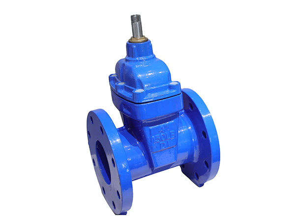
Groove resilient gate valve (grooved end resilient seated gate valve) relies on grooved pipe couplings for fast assembly, widely adopted in fire protection, building water supply and HVAC circulating water pipelines. Its installation differs greatly from flange and threaded valves; standardized groove processing, alignment and clamping steps are required to avoid joint leakage, valve jamming and coating damage. Complete installation covers pre-installation inspection, pipe groove machining, positioning assembly, coupling fastening and post-installation pressure test (Barnes, 2023).
1. Pre-Installation Inspection & Preparation
1.1 Valve & Material Inspection
Check the ductile iron valve body, EPDM rubber gate and both-end groove for crack, scratch, coating peeling and rubber damage; open and close the handwheel repeatedly to confirm flexible operation without jamming.
Verify nominal diameter, PN10/PN16 pressure grade and groove dimension match the steel pipe and grooved couplings; prepare matched rubber coupling gaskets, stainless bolts and torque wrench.
Confirm the flow arrow marked on valve body for correct medium direction reference.
1.2 Pipeline Cleaning & Pipe Preparation
Finish all pipeline cutting, welding and cooling work before valve installation; purge internal welding slag, rust and sand with compressed air or clean water. Hard impurities will scratch the elastic gate and cause permanent leakage after commissioning.
Remove burrs, welding bumps and sharp edges on pipe ends; uneven end faces lead to gasket offset and joint seepage.
Use a dedicated grooving machine to roll standard grooves on both pipe ends strictly per specification: control groove depth, width and distance from pipe end. Too deep grooves reduce pipe strength; shallow grooves cause coupling slipping under water hammer pressure.
1.3 Site Layout Requirement
Reserve sufficient space around the handwheel for daily operation and maintenance.
Prepare independent pipe supports on both sides of the valve. Never let the thin grooved valve body bear the weight of front and rear pipelines; pipeline deflection will deform the valve groove and break sealing.
The valve can be mounted horizontally or vertically; install the handwheel upward for easy operation; avoid handwheel downward for long-term outdoor damp environments to prevent shaft corrosion.
2. Core Assembly Steps
Step 1: Align pipe grooves and valve grooves
Place the valve between two grooved pipes, adjust the pipeline to keep three pieces concentric without deflection. Fully align the annular grooves of pipe ends and valve grooved ends into one continuous circular track. Keep the valve’s flow arrow consistent with actual medium flow direction.
Step 2: Install grooved coupling rubber gasket
Wrap the integral rubber gasket around the combined aligned grooves. Ensure the gasket sits fully inside the annular groove without twisting, offset or extrusion; no foreign debris trapped between gasket and metal surfaces.
Step 3: Buckle two halves of grooved coupling
Cover the gasket with upper and lower coupling shells, make the coupling lugs align symmetrically on both sides of the valve. Pass bolts through lug holes and loosely screw nuts by hand for temporary fixation. Do not fully tighten at this stage.
Step 4: Diagonal cross torque tightening
Tighten paired bolts in diagonal cross sequence (instead of clockwise circular order) with a torque wrench to apply even pressure around the whole circle. Tighten in 2–3 gradual rounds to standard torque value. Uniform compression ensures the rubber gasket closely fits all metal groove surfaces for zero leakage.
Over-tightening will crush the coupling gasket and deform ductile iron valve grooves; insufficient torque leads to water seepage under working pressure.
Step 5: Check valve operation after fastening
After all couplings are locked, rotate the handwheel full open and full closed multiple times. If obvious resistance or jamming occurs, loosen coupling bolts slightly, re-center the valve and re-tighten evenly. Misalignment of grooves is the main cause of gate clamping failure.
3. Special Installation Rules
For buried pipeline grooved resilient gate valve: Wrap the valve and couplings with anti-corrosion protective cloth before backfilling; avoid sharp stone extrusion damaging valve coating and rubber gaskets. Equip extension operation rod for underground valve wells to control the valve from ground surface.
For fire riser vertical installation: Set pipe brackets within 300mm of valve both ends to eliminate pipeline axial pulling force on grooved joints.
Do not perform welding or hot cutting near installed grooved valves; high temperature melts rubber coupling gaskets and EPDM gate lining, causing sealing failure.
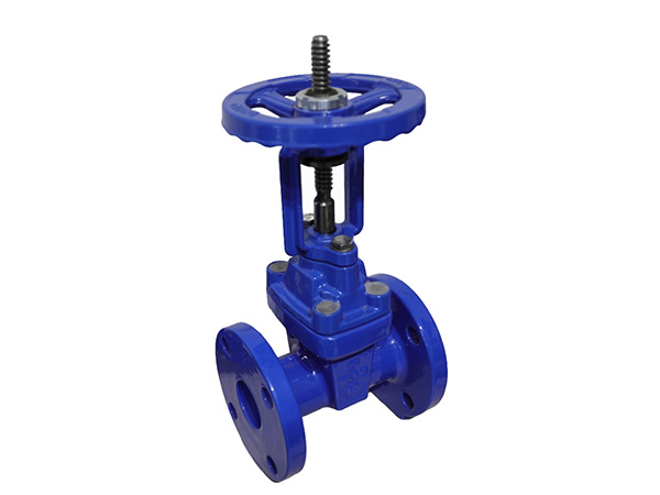
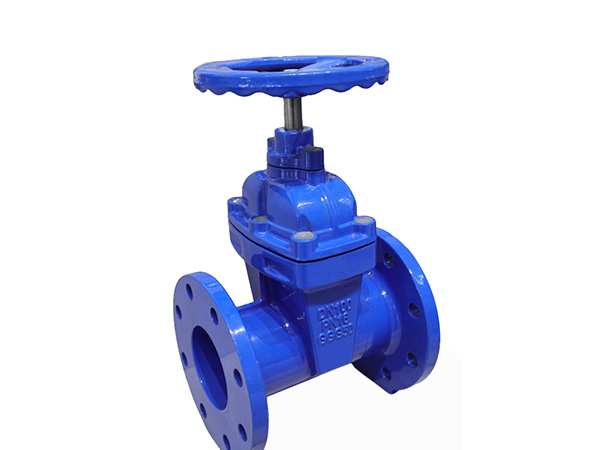
Separate installation for non-rising stem and rising stem types: Non-rising stem fits shallow valve pits and narrow pipe shafts; rising stem requires extra vertical clearance above the handwheel for stem lifting stroke.
4. Post-Installation Pressure & Leakage Test
Close the gate fully, fill the pipeline with clean water and exhaust all internal air.
Conduct hydraulic tightness test at 1.5 times nominal pressure, hold pressure for 5–10 minutes.
Inspect every grooved coupling joint, valve bonnet flange and valve stem packing for dripping or seepage. If leakage appears, re-tighten coupling bolts in diagonal order or replace damaged gaskets.
After passing the static pressure test, open and close the valve repeatedly under test pressure to verify stable sealing without recurring leakage.
5. Common Installation Mistakes & Hazards
Unqualified pipe groove machining: Coupling slips under pressure, pipeline separation risk.
Single-side pipeline support only: Valve groove deformed, long-term joint leakage.
Circular sequential bolt tightening: Uneven gasket compression, local seepage.
Welding after valve assembly: High heat aging rubber seals, complete sealing failure.
Insufficient operation space around handwheel: Difficult daily switch and maintenance.
1. APA 7th Edition
Barnes, K. (2023). Standard installation specification and leakage prevention of grooved-end resilient seated gate valves for fire protection piping. Fire Safety Journal, 138, 103927.
2. MLA 9th Edition
Barnes, Kevin. "Standard Installation Specification and Leakage Prevention of Grooved-End Resilient Seated Gate Valves for Fire Protection Piping." Fire Safety Journal, vol. 138, 2023, p. 103927,
3. GB/T 7714-2015
[1] Barnes K. Standard installation specification and leakage prevention of grooved-end resilient seated gate valves for fire protection piping[J]. Fire Safety Journal, 2023, 138: 103927.
 HOT PRODUCT
 CONTACT US